

This vehicle has been equipped with a variety of instruments as part of a driving study which is being conducted by the Virginia Tech Transportation Institute. The main goal of this study is to study the behaviors of ride-share drivers. These instruments are not the property of the driver or owner of this vehicle and should not be removed except by a trained, authorized technician.
As it may be relevant to the work you are about to perform on this vehicle, this reference will:
There are many components but only four connections between our system and the car.

If it is decided that the system should be disconnected to prevent interfering with service to the vehicle and you are in the position to do it yourself, here is a brief guide showing how to disconnect our data acquisition system. We are only connected to the vehicle network and two power connections, which are likely sharing circuits. With our power and network connections temporarily removed, the rest of the system will be completely independent of the vehicle and should not interfere with any service needed.
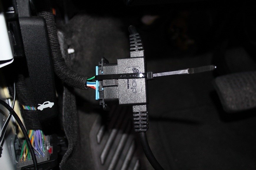
1. First, cut the zip tie and disconnect our OBDII Y cable.
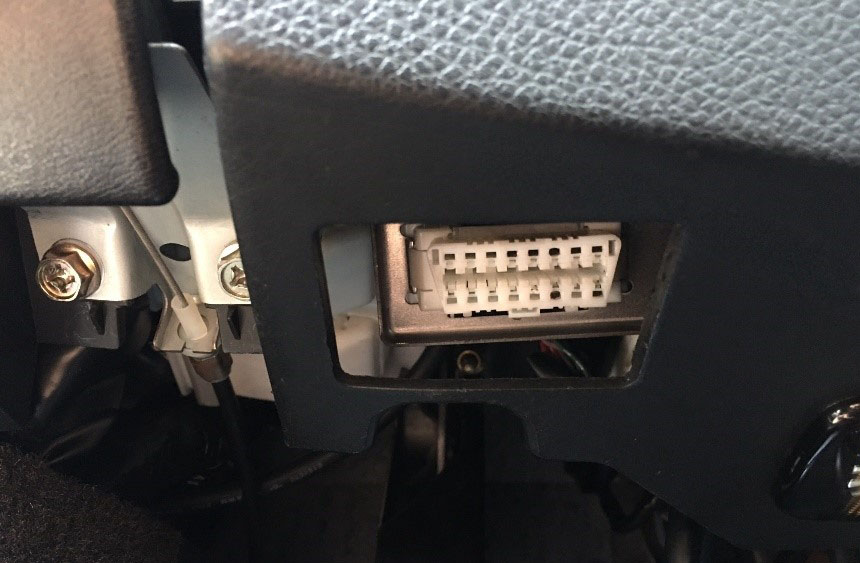
2. After unplugging, secure the Y cable and place it safely out of the way. Return the OEM OBDII connector to its original location using the factory mounting hardware.
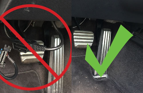
3. With the Y cable, it is important it is out of the way yet still accessible for when it needs to be reconnected.

4. Coil and zip tie the cable neatly and tuck to the side behind a panel or zip tie to the side to ensure it is not visible in the foot well and completely clear of the emergency brake, foot pedals and steering column!
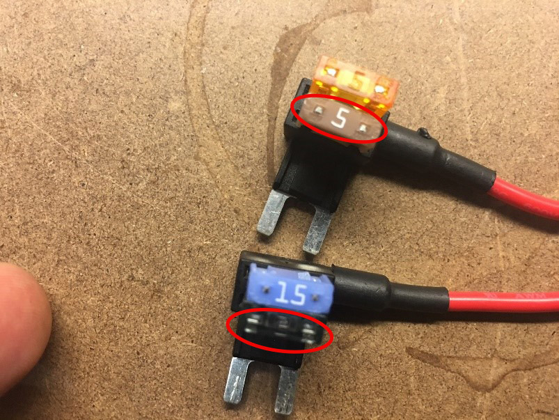
1. If found at the Fuse panel then remove the taps and secure out of the way and return the OEM fuses back to their original slots (on the taps the lower fuses circled in red will be the OEM fuses).
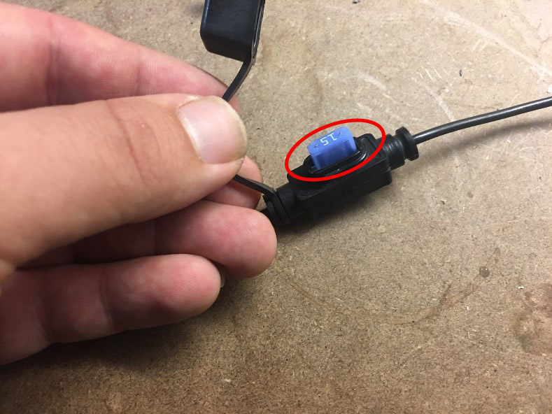
2. If posi-tapped in the wiring harness, leave taps in place and remove the fuse from the inline fuse holder.
Hardware Engineering Lab support line
540-739-9063